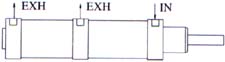
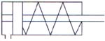
2) Single Acting
Cylinder:
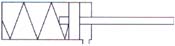 These cylinders
have power strokes in one direction only.Return Types
available are:a) Sping return:
1) Air to forward piston / spring to return
piston.2) Air to retract
piston / spring to forward piston. b) Return by external
load: Air to forward or return piston and original
position achieved by external load. These cylinders
have power strokes in one direction only.Return Types
available are:a) Sping return:
1) Air to forward piston / spring to return
piston.2) Air to retract
piston / spring to forward piston. b) Return by external
load: Air to forward or return piston and original
position achieved by external load.
|
| |
Power Stroke in
single acting cylinder is achieved only in one direction
of piston movement. Return stroke is achieved by any of
the methods mentioned above. Seed and pull force of
return stroke is dependent on the stiffness of the
spring used and the mode of flow control available.
These cylinders are used in applications where the
piston is to be in the original / neutral position in
the case of power failures
etc. |
|
| |
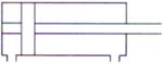
3) Double Ended
Cylinder :
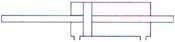 The piston rod in
this case is extended from both the sides of the piston
and the power stroke is available in both the
directions. An example could be the clamping of the
workpiece to be moved onto the cylinder body rather than
the piston shaft. The piston rod in
this case is extended from both the sides of the piston
and the power stroke is available in both the
directions. An example could be the clamping of the
workpiece to be moved onto the cylinder body rather than
the piston shaft.
|
| |
4) Tandem
Cylinder:
 These are two double
acting cylinders coupled together with a common piston rod and
find applications where there is space constraint to use a
larger bore for achieving the requisite force. These are two double
acting cylinders coupled together with a common piston rod and
find applications where there is space constraint to use a
larger bore for achieving the requisite force. 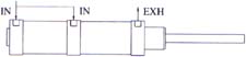 The force
achieved by a tandem cylinder is 1.8 times that of a double
acting cylinder of the same bore eg.force obtained by 200 mm
bore cylinder at 5 bar is around 1.6 tonnes. This same force
can be obtained using a tandem cylinder of bore size 150
mm. The force
achieved by a tandem cylinder is 1.8 times that of a double
acting cylinder of the same bore eg.force obtained by 200 mm
bore cylinder at 5 bar is around 1.6 tonnes. This same force
can be obtained using a tandem cylinder of bore size 150
mm.
|
| |
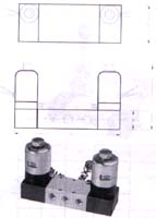
 5) Continuous
Reciprocating Type: 5) Continuous
Reciprocating Type:
Also known
depicted as linear air motor, these units are self
reciprocating air cylinders which require no external
valves or limit switches. Just one air input is required
to operate the cylinders. Speed of forward and return
stroke can be adjusted by the flow control valves
mounted on the cylinders. |
| |
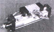
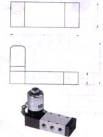
 6) Valve Mounted
Cylinder: 6) Valve Mounted
Cylinder:
This incorporates
a double acting cylinder with valve mounted directly on
it. This avoids excessive piping as just an inlet
pressure is required to be given to the inlet of the
valve. Outlets ports of the valve are pre-connected to
the ports of the cylinders. This cylinder is not
continuously reciprocating type. On / Off switches are
required to enable the forward and return
stroke. |
| |
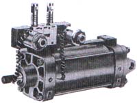
 7) Feed Control
Cylinder: 7) Feed Control
Cylinder:
In general
applications, the speed of a cylinder can be controlled
using flow control valves. However, in applications
which require very precise speed control without jerks,
the feed control cylinder is recommended.
Hydro-pneumatic system provided in the cylinder enables
achievement of velocities as low as 50 mm per
minute. |
| |
| Working Characteristics of
Pneumatic Cylinder |
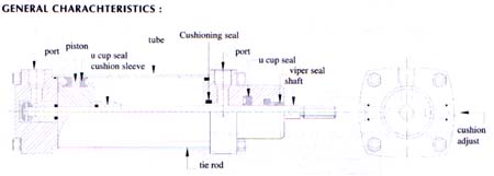 |
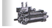
| Material Specification: |
| Cylinder
tube |
Seamless hard
drawn low carbon steel tube, honed and hard chrome
plated internally to 60 RC increases seal life. Bores:
40 to 300 mm.Seamless Hard
drawn brass tube internally polished : Bores : 19 to 65
mm |
| Piston
rod |
EN8 ground, micro
finished and hard chrome plated for lasting seal life
and corrosion resistance. |
| Seals |
Piston and cushion
seals made from a wear resistant nitrile rubber
compound. The double lip seal design automatically self
compensates against wear. |
| Piston |
Cast
iron |
| End
covers |
Cast iron oxidised
to prevent
corrosion |
|
| |
| Media |
Air, Oil and inert
gas |
| Temperature range |
-20 to 85 degrees
cen. |
| Pressure |
150 p.s.i. / 10 bar |
| Cushioning |
available in bore sizes 32 and above
only. |
|
| Note: The internal finish of brass tube has
been known to improve in continuous operation with the passage
of time thereby reducing friction. |
| |
direction control
valves
Direction Control
Valves are used for operating air / power cylinders. It is a
prerequisite to identify the correct type of valve suitable to
the relevant application. A detailed description of the types
of valves and their application is illustrated
below:
1) SPOOL TYPE: SERIES
11
2) DIRECT ACTING
TYPE: SERIES 12
3) POPPET TYPE:
SERIES 16
SPOOL TYPE VALVES
(SERIES 11)
The movement by the
piston in the cylinder is achieved by the alternate flow of
compressed air guided by the position of the spool in the
valve. The position of the spool is governed by external means
of actuation which could be manual or
electrical.
Selection of spool
valve is based on the following criteria:
1) FORWARD OPERATING
MECHANISM OF SPOOL
2) RETURN OPERATING
MECHANISM OF SPOOL
3) NUMBER OF
PORTS
4) NUMBER OF
POSITIONS
5) PORT
SIZE |
| |
| 1) FORWARD OPERATING MECHANISM OF
SPOOL |
2) RETURN OPERATING MECHANISM OF
SPOOL |
ACTUATION |
TYPES |
ACTUATION |
TYPES |
MANUAL |
Hand Lever / Foot
Pedal / Palm |
MANUAL |
Hand Lever / Foot
Pedal / Palm |
SOLENOID
COIL |
6 to 220 V D.C. 6
to 400 V A.C. |
SOLENOID
COIL |
6 to 220 V D.C. 6
to 400 V A.C. |
PILOT
AIR |
External |
PILOT
AIR |
External |
MECHANICAL |
Roller / Roller
Lever |
MECHANICAL |
Roller / Roller
Lever |
|
| |
| 3) NUMBER OF PORTS |
No. of
Ports |
Types |
PP: Pressure
port
(pressure line in) |
4) NUMBER OF
POSITIONS: (a) Two position, (b) Three
position
5) PORT
SIZE: Indicates the size of the ports of
the valve to which pipe fittings are made. Where it is
required to have higher flow rate, it is taken as a
rough assumption that the larger the port size, higher
is the flow rate leading to increase in linear speed of
cylinder. "LUTHRA" make offers port valve sizes ranging
from 1/8" B.S.P. to 3/4" B.S.P. |
2
Ports |
1 PP / 1
OP |
OP: Outlet
port |
3
Ports |
1 PP / 1 CP / 1
EP |
EP: Exhaust
port |
5
Ports |
1 PP / 2 CP / 2
EP |
CP: Compressor
port |
|
| |
| SERIES
11: SPOOL OPERATED
VALVES |
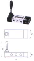
| GENERAL VALVE
CHARACTERISTICS |
HANDLEVER
OPERATED:
|
| BODY |
ALUMINIUM HARD
ANODIZED |
| SPOOL |
ENB HARD CHROME
PLATED |
| SEALS |
NITRILE /
VITON |
| TEMPERATURE |
-10 TO 80 / -10 TO
250 DEG. CEN. |
| PORT
SIZE |
1/4", 3/8", 1/2" B.
S. P. |
| MEDIA |
AIR / FLUID
* |
| PRESSURE
RANGE |
AS PER TYPE OF
VALVE |
| *: fluid media
application valid for all spool valves except for 3 port
& 5 port solenoid operated valves |
|
| |
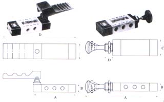
| FOOT OPERATED VALVE |
|
PALM BUTTON OPERATED |
 |
| |
TYPE |
SIZE |
A |
B |
C |
D |
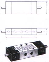
1) 5/2 Spring
return |
1/4" |
134 |
25 |
50 |
214 |
3/8" |
216 |
38 |
68 |
320 |
1/2" |
216 |
38 |
68 |
320 |
4) 3/2 Spring
return |
1/4" |
110 |
25 |
50 |
190 |
3/8" |
176 |
38 |
68 |
280 |
1/2" |
176 |
38 |
68 |
280 |
|
| |
| Pressure
range |
0 to 10
bar |
TYPE |
SIZE |
A |
B |
C |
D |
1) 5/2 Spring
return |
1/4" |
175 |
25 |
50 |
15 |
3/8" |
255 |
38 |
68 |
15 |
1/2" |
255 |
38 |
68 |
15 |
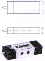
2) 5/2 Detent
type |
1/4" |
170 |
25 |
50 |
15 |
3/8" |
250 |
38 |
68 |
15 |
1/2" |
250 |
38 |
68 |
15 |
4) 3/2 Spring
return |
1/4" |
150 |
25 |
50 |
15 |
3/8" |
215 |
38 |
68 |
15 |
1/2" |
215 |
38 |
68 |
15 |
5) 3/2
detent |
1/4" |
155 |
25 |
50 |
15 |
3/8" |
220 |
38 |
68 |
15 |
1/2" |
220 |
38 |
68 |
15 |
|
| |
| Pressure
range |
2 to 10
bar |
TYPE |
SIZE |
A |
B |
C |
D |
1) 5/2 Spring
return |
1/4" |
134 |
25 |
50 |
120 |
3/8" |
216 |
38 |
68 |
150 |
1/2" |
216 |
38 |
68 |
150 |
2) 5/2 Detent
type |
1/4" |
138 |
25 |
50 |
120 |
3/8" |
209 |
38 |
68 |
150 |
1/2" |
209 |
38 |
68 |
150 |
3) 5/3
Detent |
1/4" |
138 |
25 |
50 |
120 |
3/8" |
209 |
38 |
68 |
150 |
1/2" |
209 |
38 |
68 |
150 |
4) 3/2 Spring
return |
1/4" |
109 |
25 |
50 |
120 |
3/8" |
175 |
38 |
68 |
150 |
1/2" |
175 |
38 |
68 |
150 |
5) 3/2
Detent |
1/4" |
1131 |
25 |
50 |
120 |
3/8" |
179 |
38 |
68 |
150 |
1/2" |
179 |
38 |
68 |
150 |
6) 3/3
detent |
1/4" |
113 |
25 |
50 |
120 |
3/8" |
179 |
38 |
68 |
150 |
1/2" |
179 |
38 |
68 |
150 |
|
| |
| SERIES 11: SPOOL OPERATED
VALVES |
| DOUBLE PILOT |
SINGLE PILOT |
|
PRESSURE RANGE |
2 to 10
bar |
 |
PRESSURE RANGE |
2 to 10
bar |
| TYPE |
SIZE |
A |
B |
C |
TYPE |
SIZE |
A |
B |
C |
| 1) 5/2 Detent
type |
1/4" |
138 |
30 |
50 |
1) 5/2 Spring
return
|
1/4" |
138 |
25 |
50 |
3/8" |
216 |
38 |
68 |
3/8" |
216 |
38 |
68 |
1/2" |
216 |
38 |
68 |
1/2" |
216 |
38 |
68 |
| 2) 3/2
detent |
1/4" |
115 |
30 |
50 |
4) 3/2 Spring
return
|
1/4" |
113 |
25 |
50 |
3/8" |
176 |
38 |
68 |
3/8" |
176 |
38 |
68 |
1/2" |
176 |
38 |
68 |
1/2" |
176 |
38 |
68 |
|
| |
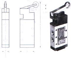
| ROLLER OPERATED |
ROLLER REVER OPERATED |
|
PRESSURE RANGE |
0 to 10
bar |
 |
PRESSURE RANGE |
0 to 10
bar |
| TYPE |
SIZE |
A |
B |
C |
D |
TYPE |
SIZE |
A |
B |
C |
| 1) 5/2 Spring
return |
1/4" |
140 |
25 |
50 |
5 |
1) 5/2 Spring
return |
1/4" |
150 |
50 |
25 |
3/8" |
222 |
38 |
68 |
5 |
1/2" |
222 |
38 |
68 |
5 |
| 4) 3/2 Spring
return |
1/4" |
125 |
25 |
50 |
5 |
4) 3/2 Spring
return |
1/4" |
125 |
50 |
25 |
3/8" |
180 |
38 |
68 |
5 |
1/2" |
180 |
38 |
68 |
5 |
|
| |
| SERIES
11: SPOOL OPERATED
VALVES |
COIL
CHARACTERISTICS |
COIL |
EPOXY MOULDED (WEATHER
PROOF) |
COIL HOUSING |
HARD CHROME
PLATED |
VOLTAGE |
6 TO 440 V a.c. / 6 TO 220 V
d.c. |
POWER CONSUMPTION |
11 WATTS |
INSULATION |
CLASS
'H' |
|
| |
 |
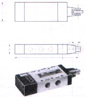
SINGLE SOLENOID OPERATED |
 |
DOUBLE SOLENOID OPERATED |
| TYPE |
SIZE |
A |
B |
C |
D |
TYPE |
SIZE |
A |
B |
C |
D |
| 1) 5/2 Spring
return |
1/4" |
145 |
30 |
50 |
105 |
1) 5/2 Retaining
type |
1/4" |
164 |
30 |
50 |
105 |
3/8" |
216 |
38 |
68 |
105 |
3/8" |
216 |
38 |
68 |
113 |
1/2" |
216 |
38 |
68 |
105 |
1/2" |
216 |
38 |
68 |
113 |
3/4" |
250 |
42 |
85 |
117 |
3/4" |
246 |
42 |
85 |
117 |
| 2) 3/2 Spring
return |
1/4" |
125 |
30 |
50 |
105 |
2) 5/3 Spring
centered |
1/4" |
194 |
30 |
50 |
105 |
| 3/8" |
260 |
38 |
68 |
113 |
3/8" |
216 |
38 |
68 |
105 |
1/2" |
260 |
38 |
68 |
113 |
4) 3/2 Retaining
type |
1/4" |
140 |
30 |
50 |
105 |
3/8" |
175 |
38 |
68 |
113 |
1/2" |
175 |
38 |
68 |
113 |
1/2" |
216 |
38 |
68 |
105 |
5) 3/3 Spring
centered |
1/4" |
170 |
30 |
50 |
105 |
3/8" |
220 |
38 |
68 |
113 |
1/2" |
220 |
38 |
68 |
113 |
|
| |
| Pressure
range |
2 to 10
bar |
|
Pressure range |
1/4", 3/8", 1/2" |
2 to 10 bar |
1/4", 3/8", 1/2" |
1.5 to 10 bar |
3/4" B.S.P. |
4 to 10 bar |
|
2.5 to 10
bar |
|
| Top |


 Alternate air supply to the cylinder is achieved by a 5
port / 4 port valve as illustrated in the section for
valves.
Alternate air supply to the cylinder is achieved by a 5
port / 4 port valve as illustrated in the section for
valves.